
TM 11-6625-2638-30
Table 2-3. Test Set Troubleshooting Continued
STEP
PROCEDURE
NORMAL INDICATION
ABNORMAL INDICATION
CORRECTIVE ACTION
37
a. Connect LED PRF jack to GRD jack.
b. Connect scope and counter returns to GRD jack.
NOTE
It may be necessary to dim the oscilloscope grid and to increase the display
brightness above normal in order to see some of the waveforms.
38
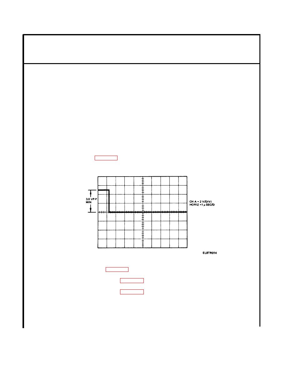
Use oscilloscope and counter to verify voltage and frequency of the pulse at J5-JJ.
Peak to Peak voltage is 3.0 volts minimum.
Frequency is 9.9 to 10.1 Hz.
No pulse.
Check wiring (para 2-12).
Less than 3 v p-p pulse.
No pulse
Check wiring (para 2-12).
Less than 3 volt pulse.
Replace circuit card (para 2-19).
Frequency off.
Replace circuit card (para 2-19).
2-14

 Previous Page
