TM 11-6625-2685-23
Table 3-2. Laser Simulator Troubleshooting - Continued
STEP
PROCEDURE
NORMAL INDICATION
ABNORMAL INDICATION
CORRECTIVE ACTION
8
Connect oscilloscope vertical input to circuit card E3 (-) and E5 (+) using x 10 probe.
NOTE
Use a hood on the scope. The pulse will appear very dim because of the
slow repetition rate.
9
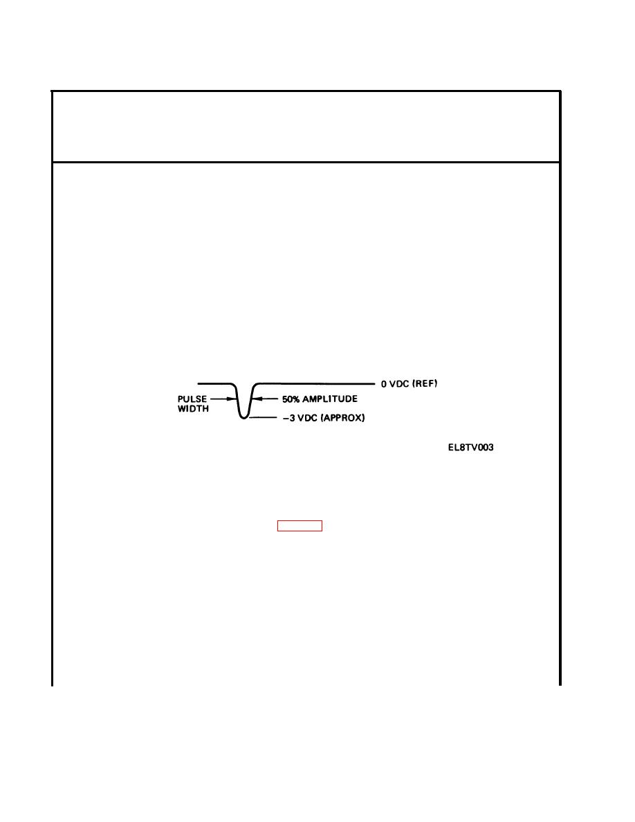
Set oscilloscope controls to measure the following pulse width at 50% amplitude level.
(Vertical input 0.1 volt cm, horizontal 0.1 sec cm.)
Pulse width is 0.025 to 0.125 sec.
Pulse width is high or low.
Replace circuit card (para 3-9).
10
Connect counter E3 (common) and E5 (signal) to circuit card using a shielded lead.
11
Set up counter to measure the (approximately 50.1 msec) period T1.
3-6


 Previous Page
